| Add a State to a State Diagram and Control Its Generated Code Using StaMa Visio Shapes |
Explains how to add a state to a StaMa Visio Shapes state diagram and control the code generated for the state.
States are added to a state diagram by draging and dropping the state shape from the Document Stencil to a region in the state diagram.
See also Create a Basic State Diagram and Generate Code from It.
Adding the state
In the Document Stencil locate the State shape and drag it over a region on the state diagram. The border of the region changes its appearance.
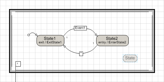 Figure 1: Dragging the new state into the region accentuates the region border
Hover over the regions in the state diagram to select the desired region. Drop the state shape. A properties dialog Shape data appears.
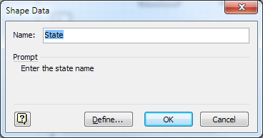 Figure 2: Create state asks for name
Enter the state name and press OK.
Generate the code into the target file e.g. by pressing Ctrl+G. Check that the new State has been added to the target file.
You can drag the state within the region. The border of the region will change its appearance when the state is moved outside of the region.
Renaming the State
Locate the state name in the diagram and double click in this area. The Shape data properties dialog of the state appears.
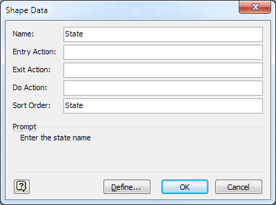 Figure 3: State properties dialog
Change the Name field and press OK to close the dialog. The state name in the diagram changes and the width of the state is adapted to the new name.
Generate the code into the target file e.g. by pressing Ctrl+G. Check that the new State has been added to the target file.
You can change the sort order of the states in the generated code by changing the Sort Order field in the above Shape data properties dialog. States are generated according to the alphabetical order of the field values in their Sort Order field.
Setting Entry and Exit Actions
Locate the state name in the diagram and double click in this area. The Shape data properties dialog of the state appears.
Change the Entry Action and/or the Exit Action field and press OK to close the dialog. The entry / and/or exit / description in the diagram changes and the width of the state is adapted to the content.
Generate the code into the target file e.g. by pressing Ctrl+G. Check that the new State has been updated properly in the target file.
The contents of the Entry Action and Exit Action field are usually speaking method names of the embedding class of the state machine. However anonymous delegates or lambda expressions are also valid content for the fields and may be perfectly reasonable for some applications.
Changing the Location of the State in the Generated Code Relative to the Other State
Locate the state name in the diagram and double click in this area. The Shape data properties dialog of the state appears.
The code generator creates the states ordered alphabetically according to the values in the Sort Order field. Considering the Sort Order field values of the other states in the same region, choose a reasonable value for this state and enter it to the Sort Order field of the dialog.
Generate the code into the target file e.g. by pressing Ctrl+G. Check that the new State has the desired relative location in the target file.
Numeric values may be a perfect choice for the Sort Order field, however please consider they are also sorted alphabetically. The Sort Order field value itself is not written into the generated code.