| States, Transitions and Regions |
Describes how to define the states and transitions for a basic state machine and what a region is.
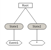
StaMa represents the structure of a state machine through a tree structure of Region, State and Transition instances, each instance represents a node in the tree.
The purpose of state and transition instances is fairly obvious.
The concept of regions is not immediately apparent from the state diagram: A Region instance is the container for states. The rule of thumb is, that a Region instance is always involved when the state machine diagram defines an initial state. Accordingly Region instances are needed for top level states, for the sub-states of a composite state and for every orthogonal sub-region. Composite states and orthogonal regions are explained later.
The tree structure is aggregated at the StateMachineTemplate instance through the StateMachineTemplate.Root property. The Region, State and Transition tree nodes are created through the factory methods Region, State and Transition of the StateMachineTemplate instance.
For a simple two state diagram with transitions between the states as in Figure 1 the corresponding tree structure can be created as shown in the subsequent code chunk.
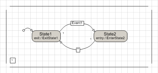
StateMachineTemplate t = new StateMachineTemplate();
t.Region("State1", false);
    t.State("State1", null, ExitState1);
        t.Transition("Transit1", "State2", "Event1", null, null);
    t.EndState();
    t.State("State2", EnterState2, null);
        t.Transition("Transit2", "State1", null, null, null);
    t.EndState();
t.EndRegion();
Writing the Region, EndRegion, State, EndState and Transition statements in this way yields a domain specific language for state machines. Nested tree nodes enclosed within a Node...EndNode scope are automatically linked as childs of the enclosing tree node.
The recommended indentation improves the visualization of the tree structure and helps reading the code.
The closing EndRegion statement (for every Region statement) and EndState statement (for every State statement) indicates that the sub-structure of the corresponding tree node has been completed. For regions the EndRegion statement indicates that all states have been specified. For states the EndState statement indicates that all transitions and all orthogonal sub-regions have been specified.
Execution of the final (balanced) EndRegion statement assigns the StateMachineTemplate.Root property and starts a syntactic check that all referenced state names are existing and unique, that the region initial states are part of the region, that the transition source states and target states are valid and other syntactic conditions. If there are syntactic errors, a StateMachineException is thrown with a Message that explains the error. The Region, State and Transition instances are immutable after the final EndRegion statement.
The OMG UML Specification suggests that transitions shall be owned by the region that contains the transition. StaMa aggregates transitions at the state where the transition starts. This choice is natural as it easily allows to find all reached candidate transitions for the active state of the state machine. |
Multiple transitions may start from the same state. These are added through a sequence of Transition statements after the State statement.
Of course only a single transition can execute at one time. In case multiple transitions of this group are eligible to be executed at the same time, the first one as appearing in the code is executed.
The below sample state diagram shows a state with three transitions that would be triggered through the same signal.
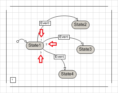
The OMG UML Specification doesn't define a precedence for transitions. In a state diagram this precedence (or priority) could be clarified by adorning each transition with a priority number. StaMa Visio Shapes provide a priority property for transitions that defines the order in which the transitions are generated. |
StateMachineTemplate t = new StateMachineTemplate();
t.Region("State1", false);
    t.State("State1", null, null);
        t.Transition("Transit1", "State2", "Event", null, null);
        t.Transition("Transit2", "State3", "Event", null, null);
        t.Transition("Transit3", "State4", "Event", null, null);
    t.EndState();
    t.State("State2", null, null);
    t.EndState();
    t.State("State3", null, null);
    t.EndState();
    t.State("State4", null, null);
    t.EndState();
t.EndRegion();
In the above sample the transition named "Transit1" will execute when calling the StateMachine.SendTriggerEvent method with the triggerEvent parameter set to "Event".