| Create a Plain Transition and Control Its Generated Code Using StaMa Visio Shapes |
Explains how to create a simple transition between two states in a StaMa Visio Shapes state diagram and control the code generated for the transition.
Common two ended transitions are composed of two shapes in in StaMa Visio Shapes:
The transition knot shape that carries the transition event signal, the guard and the transition action. This shape is connected to the source state.
A transition segment that is connected to the target state and to the transition knot.
The transition parts can be bent after being placed in order to achieve a convenient diagram layout. The shapes can be added by drag and drop from the Document Stencil to the diagram by drag and drop and can be connected later.
Adding the transition
In the Document Stencil locate the Transition Knot shape and drag it over the border of the intended source state in the state diagram.
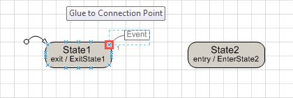 Figure 1: Drag transition knot over the source state border
Drag the line end of the transition knot over the source state border until a small red rectangle appears on the source state. Drop the transition knot shape.
In the Document Stencil locate the Transition Segment shape and drag it over the border of the intended target state in the state diagram.
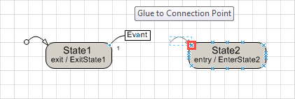 Figure 2: Drag transition segment over the target state border
Drag the line end of the transition segment with the arrow over the target state border until a small red rectangle appears on the source state. Drop the transition segment shape.
When the transition segment is selected, it has a small yellow diamond at its dangling end. Drag the small yellow diamond over the center of the transition knot box until a small red rectangle appears.
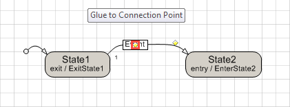 Figure 3: Drag dangling transition segment end over transition knot box
Drop (release the mouse button) to connect the dangling line end with the transition knot.
When the transition segment or the transition knot are selected, they have a second small yellow diamond which is usually not placed on the graphics of the shape. This yellow diamond defines the curvature of the shape. Drag it to modify the curvature and to achieve a convenient transition layout.
Depending on the order of adding the transition knot and the transition segment they now have an unwanted graphical z-order which causes the transition segment to cross the transition knot box. By lifting the transition knot to the topmost graphical z-order, the transition knot box will cover the transition segment which looks much better.
Open the context menu of the transition knot by right-clicking with the mouse on its line, not on the box. The context menu appears (and the two yellow diamonds).
In the context menu select Bring to front. The part of the transition segment line that crosses the transition knot box disappears.
Generate the code into the target file e.g. by pressing Ctrl+G. Check that the new Transition is properly generated in the target file.
The transition is now properly connected. In order to further arrange the state diagram, the source or target state or the yellow diamond in the center of the transition knot box can be dragged and will not disconnect the transition.
16 connection points are distributed along the state border, 3 at each side and 1 at each rounded corner of the state. Multiple transitions may start or end at a connection point.
Setting the Transition Signal Event, Guard Condition and Transition Action
Locate the transition knot box in the diagram and double click in this area. The Shape data properties dialog of the transition knot appears.
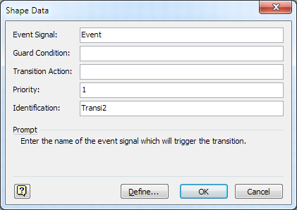 Figure 4: Transition properties
Change the Event Signal, Guard or Action field and press OK. Press OK to close the dialog. The content in the transition knot box changes and shows the transition information and the size of the transition knot box is adapted.
Generate the code into the target file e.g. by pressing Ctrl+G. Check that the modified transition properties have properly been updated in the target file.
Setting the Transition Priority to Define the Precedence of Conflicting Transitions
Transitions appearing earlier in the generated code take precedence over others in case of conflicting transitions. The Priority field of the Shape data properties dialog of the transition allows to control the order how transitions are generated in the code. The code generator creates outgoing transitions from the same state ordered alphabetically according to the values in the Priority field.
Locate the transition knot box in the diagram and double click into the box. The Shape data properties dialog of the transition knot appears (same dialog as used for setting the signal event).
The code generator creates the transitions ordered alphabetically according to the values in the Priority field. Considering the Priority field values of the other transitions outgoing from the same state, choose a reasonable value for this transition and enter it into the Priority field of the dialog. Press OK to close the dialog.
Generate the code into the target file e.g. by pressing Ctrl+G. Check that the location of the transition has properly been updated in the target file.
Setting a Human Readable Identifier for the Transition to Identify it during Tracing and Debugging
Locate the transition knot box in the diagram and double click into the box. The Shape data properties dialog of the transition knot appears (same dialog as used for setting the signal event).
The Identification field contains an automatically generated identifier for the transition that might not be speaking when it comes to tracing or debugging. Enter a meaningful name for the transition into the Identification field and press OK to close the dialog.
Generate the code into the target file e.g. by pressing Ctrl+G. Check that the transition has properly been updated in the target file.