| Create a Composite State Using StaMa Visio Shapes |
Explains how to convert a simple state into a composite state in a StaMa Visio Shapes state diagram.
Composite states contain orthogonal sub-regions, at least one. Sub-regions in turn contain states just like the root region. Through this double step recursion it is possible to create an arbitrary deep nested hierarchy of states.
This nesting hierarchy of a state machine is reproduced with StaMa Visio Shapes through the concept that the region shape is a grouping container for states and the state is a group container for regions. Regions are represented by the region shape, which is a group container that can contain multiple states.
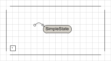
States are represented through the state shape which is usually a simple state but can be converted to a composite state that can contain one or more sub-regions.
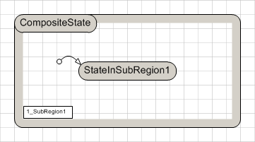
Please notice the graphical similarity of Figure 1 with the contents of the CompositeState in Figure 2. Essentially these contents are created by adding the same graphical objects as in Figure 1 into a Microsoft Visio group object that is made available through the embedding state.
Converting the Simple State Shape to a Composite State Shape
Convert the simple state into a group container that can accept sub-regions:
Locate the simple state in the state diagram. Make sure there is some blank space below and to the right of the state.
Open the context menu of the state e.g. by right clicking the state and execute the menu item Convert to Composite State.... The simple state expands its size and provides now an inner area. When the state is selected, it can now be resized by dragging the selection handles.
Add a region to the composite state:
Open the context menu of the state e.g. by right clicking the state and execute the menu item Configure Sub-Regions.... A new window opens containing an empty drawing area.
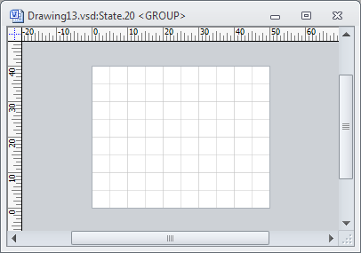 Figure 3: Configure sub-regions window
The window represents the contents of composite state. Arrange the new window so that both the Document Stencil and the new window are visible in the Microsoft Visio application.
In the Document Stencil locate the Region shape and drag and drop it to the contents window of the composite state.
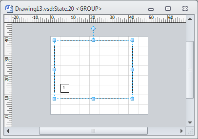 Figure 4: Sub-region of composite state dropped
Resize the dropped region shape to exactly match the size of the entire drawing area.
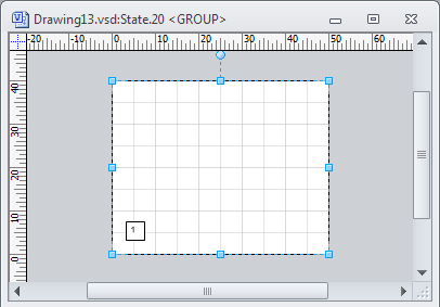 Figure 5: Second sub-region of composite state aligned
Close the configure sub-regions window of the composite state.
Add a simple state to the composite state:
Drag a State shape from the Document Stencil to the composite state and drop it as described in Add a State to a State Diagram and Control Its Generated Code.
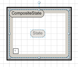 Figure 6: Dragging the state into the sub-region. Region border changes appearance
Define the newly added simple state as the initial state of the region:
In the Document Stencil locate the Transition Segment shape and drag it over the border of the simple state in the composite state. Drag the line end of the transition segment with the arrow over the target state border until a small red rectangle appears on the source state. Drop the transition segment shape.
Convert the transition segment to an initial state marker:
Double click the transition segment. The Shape data properties dialog of the transition segment appears. In the Segment Type combo box select Initial state.
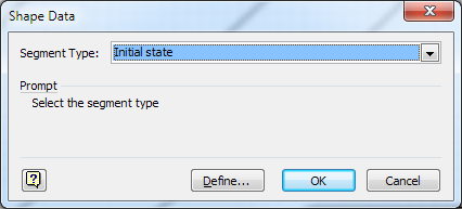 Figure 7: Transition segment properties dialog
Press OK to close the dialog.
Generate the code into the target file e.g. by pressing Ctrl+G. Verify that in the target file the composite state has a sub-region and adresses the simple state in the sub-region as the initial state.
The target file can be opened through the Open Target File context menu item of the code generator shape and will be opened in the operating system default editor.
The composite state now contains one sub-region that can host states. Add simple states to the composite state through drag and drop as described in Add a State to a State Diagram and Control Its Generated Code. It is not neccessary to open the contents window of the composite state except for adding another sub-region.