| Add a Second, Orthogonal Region to a Composite State Using StaMa Visio Shapes |
Explains how to add second (or any other), orthogonal region to a composite state in a StaMa Visio Shapes state diagram.
Composite states can contain multiple orthogonal sub-regions, each of these sub-regions in turn contain states, one of the states in each sub-region must be marked as the initial state.
The multiple orthogonal sub-regions are represented through separate region shapes that are graphically embedded into the graphical group provided through the composite state that contains them.
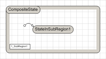
A composite state can be extended with additional, orthogonal regions.

Adding a second, orthogonal region to a composite state
Locate a composite state with one sub-region or execute Create a Composite State to create such a composite state. The composite state may have one or multiple sub-states, for simplicity the following description uses the composite state from Figure 1. Make sure there is some blank space to the right of the state.
Select the composite state and double its width by dragging the right border selection handle.
 Figure 3: Composite state enlarged
Open the context menu of the state e.g. by right clicking the state and execute the menu item Configure Sub-Regions.... A window named ... <GROUP> opens, containing the existing sub-region.
Select the sub-region by clicking on the border or on the region order rectangle and reduce its width by dragging the right border selection handle.
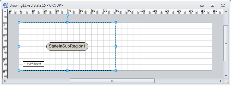 Figure 4: Sub-region of composite state reduced
Arrange the ... <GROUP> window so that both the Document Stencil and the window are visible in the Microsoft Visio application.
In the Document Stencil locate the Region shape and drag and drop it to the contents window of the composite state.
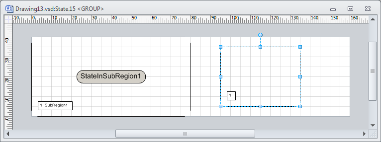 Figure 5: Second sub-region of composite state dropped
Resize the dropped region shape to exactly match the size of the entire drawing area.
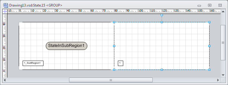 Figure 6: Second sub-region of composite state resized
Close the ... <GROUP> window of the composite state. The composite state should now look similar to Figure 7.
 Figure 7: Composite state with two sub-regions
Define the execution order of the sub-regions:
Double click the region execution order rectangle. The Shape data properties dialog of the region appears. In the Execution Order edit box enter "2_SubRegionB".
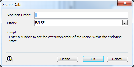 Figure 8: Region properties dialog
Press OK to close the dialog.
Add an initial state to the second sub-region:
Drag a State shape from the Document Stencil to the composite state and drop it as described in Add a State to a State Diagram and Control Its Generated Code.
 Figure 9: Dragging the state shape to the second sub-region
In the Document Stencil locate the Transition Segment shape and drag it over the border of the new simple state of the second sub-region. Drag the line end of the transition segment with the arrow over the target state border until the small red rectangle appears on the source state. Drop the transition segment shape.
Double click the transition segment. The Shape data properties dialog of the transition segment appears. In the Segment Type combo box select Initial state.
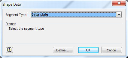 Figure 10: Transition segment properties dialog
Press OK to close the dialog.
Generate the code into the target file e.g. by pressing Ctrl+G. Verify that in the target file the composite state has a sub-region and that it adresses the simple state in the sub-region as the initial state.
The target file can be opened through the Open Target File context menu item of the code generator shape and will be opened in the operating system default editor.
The composite state now contains two sub-region that can host states. Further orthogonal sub-regions can be added the same way.