| Generate Code for Enumerations of States, Signal Events and Actions from a Diagram Using StaMa Visio Shapes |
Describes how to add a basic code generation to a state diagram and how to generate enumerations of state names, signal events or action names used in the state diagram.
The main objective of code generation is to extract code for the StaMaStateMachineTemplate structure from the Microsoft Visio state diagram. In addition to that code often requires state names, signal events, action method names and such as enumerations or lists.
The StaMa Visio Shapes code generation is conveyed through the Code generator shapes. A Code generator shape must be attached to the root region of a state diagram and will generate code into a .cs file that can be specified in the properties of the shape. Multiple Code generator shapes may be attached to the root region, each generating a separate code chunk into the same (or if needed a different) file. Generated code chunks have a marker frame of comments that surrounds the C# code to identify the begin and end of a code chunk. The frame enables the code generator to identify the code chunk on subsequent code generation actions and to update the content.
//## Begin StateMachineTemplate10
// Generated from <file:E:\Drawing1.vsd>
// at 30-02-2014 10:17:51 using StaMaShapes Version 2

...

//## End StateMachineTemplate10
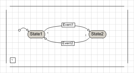
The following procedures will use a simple state machine diagram as in Figure 1 below. To keep things simple, the state machine has two states named "State1" and "State2" and two transitions triggered through "Event1" and "Event2".
Adding basic code generation for the state machine structure
In the Document Stencil locate the Code Generator shape and drag it over the region execution order rectangle of the root region in the diagram.
Drag the code generator shape until a small red rectangle appears on the region execution order rectangle.
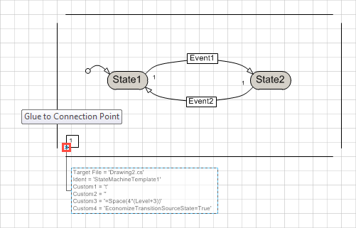 Figure 2: Drag code generator shape over the region execution order rectangle
Drop the code generator shape. A properties dialog Shape data appears.
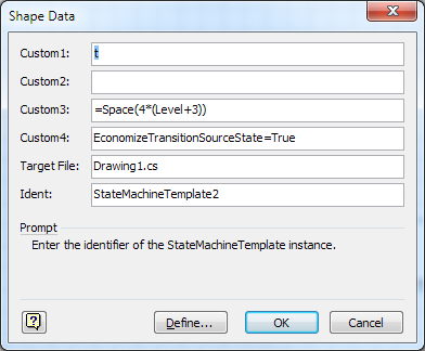 Figure 3: Basic properties of code generator shape
In the Custom1 field enter the identifier for the StateMachineTemplate instance that is used in the code.
Leave the Custom2 field empty. It is not used by the code generator.
In the Custom3 field enter a Visual Basic Script expression that evaluates to the desired indentation of nested regions and states. The default is 4 spaces of indentation per level and a general indentation of 4 * 4 spaces to accomodate for namespace, class, and method scopes.
The Custom4 field contains the EconomizeTransitionSourceState=True option string that instructs the code generator to omit the source state in the generated Transition statement if possible. Keep the setting unless source states shall be explicitly generated.
In the Target File field enter the path of the target file or leave it unchanged if it already matches. The default content is the path of the Microsoft Visio diagram file with a .cs extension and will be updated when the Microsoft Visio diagram file is moved or renamed.
In the Ident field enter an identifier that allows the code generator to locate the generated chunk within the target file in order to update the code on subsequent code generation actions. The default content is generated from the shape id in the Visio diagram and should therefore already be unique, so it can usually be kept as is.
Press OK to close the dialog.
Generate the code into the target file e.g. by pressing Ctrl+G.
Open the target file and verify that it contains a code chunk that starts with a line //## Begin <ident> and has the expected content. The target file can be opened through the Open Target File context menu item of the code generator shape and will be opened in the operating system default editor.
The contents of the generated file for the state machine from Figure 1 should now look like this:
CodeGeneratorDemo.cs//## Begin StateMachineTemplate10 // Generated from <file:E:\Drawing1.vsd> // at 30-02-2014 10:17:51 using StaMaShapes Version 2 t.Region(State1, false); t.State(State1, null, null); t.Transition(Transi4, State2, Event1, null, null); t.EndState(); t.State(State2, null, null); t.Transition(Transi6, State1, null, null, null); t.EndState(); t.EndRegion(); //## End StateMachineTemplate10
By adding the using declarations, a namespace, a class and a handy getter method this code chunk can be transformed into an appropriate class that might look as below. Please observe that the generated code is now placed in the middle of a .cs file and subsequent code generator actions will overwrite the contents of the chunk while leaving the rest unchanged.
CodeGeneratorDemoWithClass.csusing System; using StaMa; namespace CodeGeneratorDemo { class CodeGeneratorDemo { private StateMachineTemplate m_stateMachineTemplate; private StateMachineTemplate GetStateMachineTemplate() { if (m_stateMachineTemplate == null) { StateMachineTemplate t = new StateMachineTemplate(); //## Begin StateMachineTemplate10 // Generated from <file:E:\Drawing4.vsd> // at 30-02-2014 10:18:51 using StaMaShapes Version 2 t.Region(State1, false); t.State(State1, null, null); t.Transition(Transi4, State2, Event1, null, null); t.EndState(); t.State(State2, null, null); t.Transition(Transi6, State1, Event2, null, null); t.EndState(); t.EndRegion(); //## End StateMachineTemplate10 m_stateMachineTemplate = t; } return m_stateMachineTemplate; } } }
The generated code chunk now contains the statements for the structural definition as needed for the StateMachineTemplate definition. In order to make it compiling, the identifiers State1, State2, Transi4, Transi6 are missing as well as the event signal names Event1 and Event2. The StateMachineTemplate methods require state and transition names as Strings. Event signal names may be any type, but for simplicity we choose them here to be Strings also. These Strings should be defined as constants in order to let the compiler detect typing errors. The next procedure shows how to add for every identifier a static readonly member to the class.
Adding code generation for state name constants
In the Document Stencil locate the Consts Code Generator shape and drag it over the region execution order rectangle of the root region in the diagram.
Drag the code generator shape until a small red rectangle appears on the region execution order rectangle. For the moment ignore that the new shape hides or overlaps the existing Code Generator shape. It can be moved later.
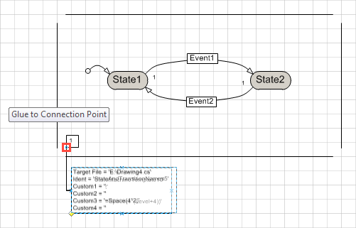 Figure 4: Drag code generator shape over the region execution order rectangle
Drop the code generator shape. A properties dialog Shape data appears.
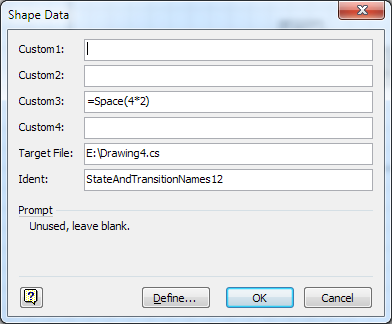 Figure 5: Basic properties of code generator shape
In the Custom3 field enter a Visual Basic Script expression that evaluates to the desired indentation of nested regions and states. The default is 2 * 4 spaces of indentation to accomodate for namespace and class scopes.
Leave the Custom1, Custom2 and Custom4 fields empty. They are not used by the code generator.
In the Target File field enter the path of the target file or leave it unchanged if it already matches. The default content is the path of the Microsoft Visio diagram file with a .cs extension and will be updated when the Microsoft Visio diagram file is moved or renamed.
In the Ident field enter an identifier that allows the code generator to locate the generated chunk within the target file in order to update the code on subsequent code generation actions. The default content is generated from the shape id in the visio diagram and should therefore already be unique, so it can usually be kept as is.
Press OK to close the dialog.
Locate the small yellow diamond at the bottom left corner of the new code generator shape. Drag it to move the shape to a favorable location.
In case the connector line of the new code generator shape crosses the earlier added code generator shape, lift the bottom code generator shape to the topmost graphical z-order. To do this open the context menu of shape that is below the line and select Bring to front in the context menu.
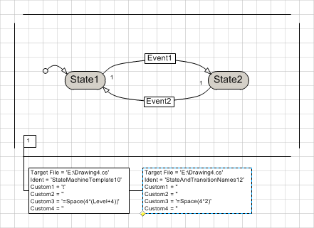 Figure 6: Arrange the overlapping consts code generator shape
Generate the code into the target file e.g. by pressing Ctrl+G.
Open the target file and verify that at the end of the file it has a new code chunk that starts with a line //## Begin <ident> and has the expected content.
Move the entire code chunk including the //## Begin <ident> and //## End <ident> lines into the class scope.
The result for the state machine from Figure 4 should now look like this:
CodeGeneratorDemoComplete.csusing System; using StaMa; namespace CodeGeneratorDemo { class CodeGeneratorDemo { //## Begin StateAndTransitionNames12 // Generated from <file:E:\Drawing4.vsd> // at 09-16-2014 21:06:11 using StaMaShapes Version 2 private static readonly string State1 = "State1"; private static readonly string Transi4 = "Transi4"; private static readonly string Event1 = "Event1"; private static readonly string State2 = "State2"; private static readonly string Transi6 = "Transi6"; private static readonly string Event2 = "Event2"; //## End StateAndTransitionNames12 private StateMachineTemplate m_stateMachineTemplate; private StateMachineTemplate GetStateMachineTemplate() { if (m_stateMachineTemplate == null) { StateMachineTemplate t = new StateMachineTemplate(); //## Begin StateMachineTemplate10 // Generated from <file:E:\Drawing4.vsd> // at 09-16-2014 21:06:11 using StaMaShapes Version 2 t.Region(State1, false); t.State(State1, null, null); t.Transition(Transi4, State2, Event1, null, null); t.EndState(); t.State(State2, null, null); t.Transition(Transi6, State1, Event2, null, null); t.EndState(); t.EndRegion(); //## End StateMachineTemplate10 m_stateMachineTemplate = t; } return m_stateMachineTemplate; } } }
The class is now compiling and can be extended with written code or updated with generated code from the diagram.
In case the event signal constants need to be part of a public interface, an additional Consts Code Generator shape can be added to the diagram and both can be adapted to generate only the corresponding subsets of identifiers. Details about the code generator capabilities can be found in Code Generator Shape.