| Create a Join Transition Using StaMa Visio Shapes |
Explains how to extend a standard transition with additional transition source states to create a join transition in a StaMa Visio Shapes state diagram.
Join transitions are transitions that require that a specific state configuration is active multiple states within different sub-regions of a composite state like Figure 1.

Join transitions are composed of the same shapes as two ended transitions but have two or more additional transition segment shapes that address the source states.
The steps for creating a join transition are similar to the steps for the two ended transitions in Create a Plain Transition and Control Its Generated Code.
The following description assumes a a composite state with two sub-regions each containing a simple state as the source states and a simple state as the target state. A description how to create a composite state with multiple sub-regions can be found in Add a Second, Orthogonal Region to a Composite State.
Creating the transition knot and defining the transition anchor state
In the Document Stencil locate the Transition Knot shape and drag it over the border of the composite state in the state diagram.
Drag the line end of the transition knot over the composite state border until a small red rectangle appears on the composite state.
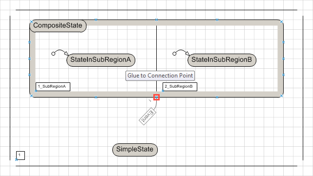 Figure 2: Drag transition knot over the source state border
Drop the transition knot shape.
The composite state itself is not the source state of the join transition, therefore the transition knot connection from the composite state has to be declared as the transition anchor:
Double click the transition knot connection line. The Shape data properties dialog of the transition knot connection appears. In the Segment Type combo box select Anchor only.
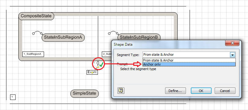 Figure 3: Convert transition segment to source state.
Press OK to close the dialog.
The transition knot is now prepared to be connected to the real source states.
Properties of the transition like the signal event, a guard condition, a transition action, the priority and a human readable identifier can be set as described in Create a Plain Transition and Control Its Generated Code.
Defining the first source state of the transition
In the Document Stencil locate the Transition Segment shape and drag it over the border of the source state in the first sub-region.
Drag the line end of the transition segment with the arrow over the source state border until a small red rectangle appears on the source state.
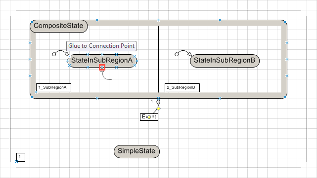 Figure 4: Drag transition segment over the source state border
Drop the transition segment shape.
When the transition segment is selected, it has a small yellow diamond at its dangling end. Drag the small yellow diamond over the center of the transition knot box until a small red rectangle appears.
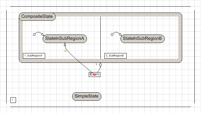 Figure 5: Drag dangling transition segment end over transition knot box
Drop (release the mouse button) to connect the dangling line end with the transition knot.
Convert the transition segment to a source state reference:
Double click the transition segment. The Shape data properties dialog of the transition segment appears. In the Segment Type combo box select From state.
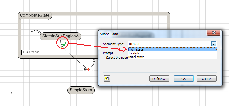 Figure 6: Convert transition segment to source state.
Press OK to close the dialog.
The transition segment may start on any nested state of the transition anchor state.
In case the transition segments starts on a state outside of the anchor state and the resulting source state configuration is still valid, the outside state contributes to the enabled condition of the transition.
Defining the second source state of the transition
Repeat the above steps for the second source state.
The diagram should now look as in Figure 7.
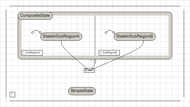 Figure 7: Join transition intermediate result after adding second source state.
An arbitrary number of source states can be added this way. Consistency of the resulting state configuration will be checked at runtime of the generated state machine.
Defining the target state of the transition
In the Document Stencil locate the Transition Segment shape and drag it over the border of the intended target state in the state diagram.
Drag the line end of the transition segment with the arrow over the target state border until a small red rectangle appears on the source state.
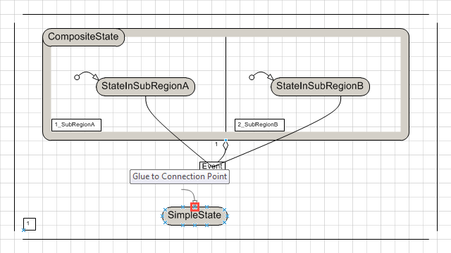 Figure 8: Drag transition segment over the target state border
Drop the transition segment shape.
When the transition segment is selected, it has a small yellow diamond at its dangling end. Drag the small yellow diamond over the center of the transition knot box until a small red rectangle appears.
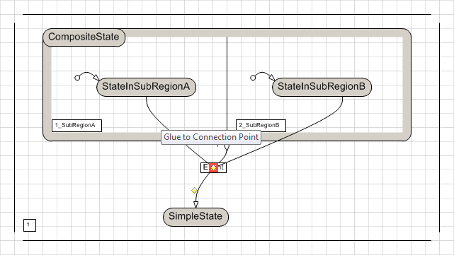 Figure 9: Drag dangling transition segment end over transition knot box
Drop (release the mouse button) to connect the dangling line end with the transition knot.
The transition target may also be a nested state within a sub-region of a state.
In case the transition shall fork to multiple sub-regions, the single transition segment can be replaced with multiple transition segments as described in Create a Fork Transition
Improving the visual appearance of the transition
Depending on the order of adding the transition knot and the transition segment they now have an unwanted graphical z-order which causes the transition segment to cross the transition knot box. By lifting the transition knot to the topmost graphical z-order, the transition knot box will cover the transition segment which looks much better.
Open the context menu of the transition knot by right-clicking with the mouse on its line, not on the box. The context menu appears (and the two yellow diamonds).
In the context menu select Bring to front. The part of the transition segment line that crosses the transition knot box disappears.
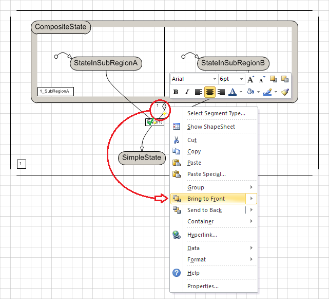 Figure 10: Bring transition knot shape to front
The transition knot position, the transition knot connection line routing and transition segment line routing may be adapted as described in Create a Plain Transition and Control Its Generated Code.
Checking the generated code
Generate the code into the target file e.g. by pressing Ctrl+G. Check that the transition has properly been generated, the target file should now contain a piece of code similar to the following:
JoinTransition.cst.Region(CompositeState, false); t.State(CompositeState, null, null); t.Transition(TransiNN, new string[] {StateInSubRegionA, StateInSubRegionB}, SimpleState, Event, null, null); t.Region(StateInSubRegionA, false); t.State(StateInSubRegionA, null, null); t.EndState(); t.EndRegion(); t.Region(StateInSubRegionB, false); t.State(StateInSubRegionB, null, null); t.EndState(); t.EndRegion(); t.EndState(); t.State(SimpleState, null, null); t.EndState(); t.EndRegion();